What Are the Most Common XPS Extrusion Line Bottlenecks, and Which Retrofit Options Work Best?
October 12, 2026
Common XPS extrusion line bottlenecks include unstable melt pressure, inconsistent foam cells, uneven board thickness, limited cooling capacity, and outdated control systems. Manufacturers can often resolve these problems through targeted retrofits instead of replacing the entire production line. The right solution depends on the root cause, current equipment condition, product specifications, and production targets. For example, a line with fluctuating board thickness may need better melt-pressure control or die maintenance, while a line with inconsistent CO₂ foaming may require improvements to gas metering, mixing, and melt cooling. A structured diagnosis helps manufacturers distinguish process problems from mechanical limitations and invest in upgrades that deliver measurable production benefits.
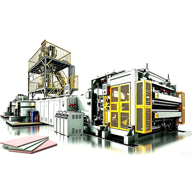
1. How Can Manufacturers Identify the Main Bottlenecks in an XPS Extrusion Line?
An XPS production line combines polymer melting, blowing-agent injection, melt mixing, cooling, die extrusion, foam expansion, calibration, and downstream handling. A bottleneck in one section can affect the entire process. Increasing extruder speed will not improve output if the die, cooling system, or haul-off equipment cannot maintain stable operation.
The first step is to establish a reliable production baseline. Record output, line speed, melt pressure, actual melt temperature, motor load, CO₂ consumption, board dimensions, density, and scrap rate. Compare these figures across several production runs and product specifications.
When evaluating equipment upgrades or planning a new line, an experienced XPS extrusion line manufacturer can help assess production capacity, board specifications, and equipment configuration.
Separate process instability from equipment limitations
A process issue often appears after changes in resin grade, blowing-agent formulation, operating conditions, or production scheduling. Operators may restore stable output by adjusting parameters within the equipment’s normal operating range.
An equipment limitation behaves differently. The line may repeatedly reach its motor-load limit, struggle to maintain melt pressure, or fail to provide sufficient cooling at the target output. In these cases, routine parameter adjustments cannot fully resolve the problem.
Use the following questions to narrow the investigation:
- Does the problem occur continuously or only during product changes?
- Does it affect every board thickness and density, or only selected specifications?
- Do pressure, temperature, and motor load fluctuate before the defect appears?
- Does the problem become worse as line speed increases?
- Has maintenance identified wear, leakage, restricted flow, or control-system faults?
For example, a plant may produce acceptable 30 mm boards but experience unstable thickness when switching to 80 mm products. This pattern points toward a capacity or process-window limitation. The team should examine cooling performance, die settings, foam expansion, and downstream handling before considering a larger extruder.
Track losses that affect commercial output
Rated capacity alone does not show how efficiently a line performs. A machine may reach its nominal output during short trials but lose production time through frequent adjustments, rejected boards, cleaning, and product changeovers.
Measure saleable output rather than relying only on kilograms processed per hour. Include startup waste, off-specification material, downtime, and the labor required to maintain stable operation. These figures help determine whether a retrofit will improve production economics.
A useful baseline should include at least three categories:
- Throughput: saleable output per hour and per shift.
- Quality: thickness variation, density consistency, surface condition, and dimensional stability.
- Reliability: unplanned stops, maintenance hours, and time spent adjusting process parameters.
This information provides a practical basis for comparing retrofit proposals and setting acceptance criteria.
2. Which Process Bottlenecks Most Often Reduce XPS Board Quality and Output?
XPS board quality depends on interactions between resin behavior, blowing-agent distribution, melt temperature, pressure, die flow, and cooling. A defect rarely identifies one failed component by itself. Operators should connect the visible symptom with process data before changing equipment.
Unstable melt pressure and fluctuating output
Pressure fluctuations can produce inconsistent discharge rates, changing board dimensions, and irregular foam expansion. Possible causes include inconsistent feeding, screw or barrel wear, temperature-control problems, restricted flow paths, and unstable blowing-agent injection.
Start by comparing melt pressure with screw speed, motor load, actual melt temperature, feeder output, and CO₂ dosing records. Check whether pressure changes precede the board defect or follow it. This sequence helps identify the likely source.
If the mechanical condition remains sound, improved pressure sensing and closed-loop control may reduce unnecessary operator adjustments. If worn screw flights or barrel surfaces cause inadequate conveying or mixing, a screw refurbishment or replacement may offer better results.
Increasing screw speed without identifying the cause can make matters worse. Higher speed may increase shear heating, change residence time, or push downstream equipment beyond its stable operating range.
Inconsistent foam cells and CO₂ distribution
CO₂-based foaming presents specific process-control challenges. Gas must disperse through the polymer melt under suitable pressure and temperature conditions. The system must also maintain enough pressure to prevent premature expansion before the melt reaches the die.
Poor gas distribution can lead to uneven cells, rough surfaces, open-cell regions, corrugation, or inconsistent density. Research on polystyrene foam extrusion also identifies surface defects and open-cell structures as possible challenges when CO₂ serves as the blowing agent.
For plants considering upgrades to their foaming process, the XPS extrusion equipment provides a reference for evaluating supercritical CO₂ foaming technology and its suitability for the target production process.
The diagnosis should cover the complete gas-to-melt path:
- CO₂ supply pressure and injection stability
- Metering accuracy and response time
- Injection-point condition and sealing
- Melt mixing and residence time
- Pressure retention before the die
- Melt cooling and temperature uniformity
- Die flow distribution and operating conditions
A retrofit may involve more accurate mass-flow measurement, improved injection controls, revised mixing components, or changes to the cooling and pressure-control arrangement. The appropriate solution depends on the existing line design and the formulation.
For example, if gas dosing fluctuates while melt pressure remains stable, the team should inspect the supply and metering system first. If dosing remains consistent but cell structure changes with output, melt mixing, temperature, and die conditions deserve closer attention.
Uneven board thickness and density
Thickness variation can originate at several points. Uneven die flow may create a nonuniform initial profile, while inconsistent foam expansion can change the final dimensions. Cooling differences and unstable haul-off speeds can further increase variation.
Map thickness across the board width and along the production direction. A persistent cross-width pattern may indicate die-flow imbalance or temperature differences. Repeating variations along the board may point to pressure fluctuations, inconsistent foaming, or downstream speed instability.
Density variation requires a separate check. Two boards with similar thickness can still differ in weight and internal structure. Measure density across representative positions and compare it with pressure, temperature, gas consumption, and material-feed records.
Avoid using die-gap adjustments to compensate for every dimensional problem. Such changes may improve one measurement while creating uneven internal structure or additional stress elsewhere in the board.
Surface defects, warpage, and dimensional instability
Surface lines, roughness, corrugation, edge defects, and board warpage can arise from different causes. Die contamination, uneven die temperature, unstable melt flow, inconsistent cooling, and excessive mechanical stress all deserve investigation.
Check the die lips and flow surfaces for buildup or damage. Verify temperature uniformity across controlled zones and inspect the calibration and cooling sections. Downstream equipment should support the board without applying uneven pressure or introducing unnecessary deformation.
A board that looks acceptable at the die exit may still warp during cooling or after cutting. Quality checks should therefore cover the product at multiple points, including after the board reaches a stable condition.
Table 1. Common XPS extrusion bottlenecks, symptoms, and first retrofit options
| Bottleneck | Typical symptoms | Initial checks | Potential retrofit |
|---|---|---|---|
| Melt-pressure instability | Output fluctuations, changing dimensions | Pressure trend, feeding, temperature, screw condition | Pressure sensors, control upgrades, screw or barrel service |
| CO₂ dosing instability | Density variation, inconsistent cells | Supply pressure, metering, injection seals | Improved dosing equipment and closed-loop control |
| Poor melt mixing | Uneven cell structure, inconsistent board quality | Mixing elements, residence time, melt temperature | Screw or mixer redesign, subject to process validation |
| Die-flow imbalance | Cross-width thickness variation, edge defects | Die cleanliness, temperature profile, flow distribution | Die refurbishment, lip adjustment, flow-path modification |
| Insufficient cooling | Warpage, dimensional instability, limited line speed | Cooling capacity, temperature uniformity, residence time | Cooling-system upgrade or revised thermal control |
| Unstable haul-off | Variable board dimensions, surface damage | Drive synchronization, belt condition, pulling force | Drive retrofit, speed synchronization, handling improvements |
| Outdated controls | Frequent manual corrections, slow changeovers | Sensor condition, control response, data availability | PLC, HMI, sensor, and drive-control upgrades |
These options are starting points rather than universal prescriptions. A retrofit should follow measurements that identify the actual constraint.
3. Which Mechanical and Control-System Retrofits Deliver the Greatest Value?
A retrofit should address a documented production loss. The best investment is not necessarily the most extensive upgrade. In many plants, a small improvement to measurement, temperature control, or mechanical condition can restore stable output. More complex changes make sense when the existing design limits the required product range or production target.
Upgrade the control system before replacing major equipment
Older lines may rely on separate controllers, manual setpoint changes, or limited production records. Operators then depend on experience to keep pressure, temperature, and line speed within an acceptable range.
A modern control retrofit can integrate key measurements and operating adjustments. Depending on the machine architecture, this may include:
- PLC and HMI replacement or modernization
- Melt-pressure and temperature monitoring
- CO₂ flow measurement and dosing control
- Synchronization of screw speed, haul-off speed, and downstream drives
- Alarm management and trend recording
- Recipe storage for approved product specifications
Better visibility can shorten troubleshooting time and make repeat orders more consistent. However, automation cannot compensate for worn components, undersized cooling systems, or an unsuitable screw design.
Before implementation, define the control functions that matter most. Retaining compatible equipment can reduce cost and commissioning time, while replacing incompatible or unreliable components may improve long-term maintainability.
Improve screw, barrel, and melt-mixing performance
Screw and barrel wear can reduce conveying efficiency, alter pressure generation, and undermine consistent processing. A line may require progressively higher settings to maintain output, yet still produce unstable melt quality.
Inspect wear against the equipment manufacturer’s tolerances. Review motor load, output at comparable screw speeds, melt temperature, and pressure behavior. If the screw remains mechanically sound, process adjustments may be sufficient. If wear or the original screw design limits performance, refurbishment or redesign may be justified.
Screw modifications require particular care on foam extrusion lines. A new geometry can change shear heating, mixing efficiency, residence time, and pressure behavior. These changes also affect how the melt handles dissolved CO₂.
The retrofit supplier should assess the resin grade, target density, blowing-agent formulation, output range, and downstream die before proposing a design. Trial runs should confirm that the change improves stability without damaging cell structure or increasing energy use.
Retrofit the die and downstream cooling section
A die retrofit can address flow imbalance, worn surfaces, limited adjustment capability, or an unsuitable operating window. The objective is uniform discharge across the board width, not simply a higher output rate.
Inspect the die for contamination, wear, temperature differences, and restricted flow. Where the design permits, a refurbishment or improved adjustment mechanism may solve the problem without a complete replacement.
Cooling deserves equal attention. The line must manage the thermal conditions required for controlled expansion and dimensional stability. If cooling capacity becomes the limiting factor, a larger extruder may increase the imbalance rather than improve saleable output.
Potential upgrades include improved temperature-control equipment, revised cooling distribution, better instrumentation, or changes to downstream support and handling. Validate each option against board thickness, density, line speed, and the time required for the product to stabilize.
Improve drive synchronization and downstream handling
An extruder can deliver a stable melt while downstream equipment creates dimensional variation. Uneven pulling force, fluctuating belt speed, poor alignment, or inconsistent cutting can damage the board or reduce usable yield.
Check the relationship between extrusion output and haul-off speed. Inspect drives, belts, rollers, calibration components, and cutting equipment. Record whether defects begin before or after the board enters downstream sections.
Drive upgrades can improve speed coordination and reduce abrupt changes during startup or product transitions. However, changing haul-off speed alone may only conceal upstream instability. Confirm the source before adjusting the production sequence.
Evaluate retrofit options by their expected return
Compare each proposal using the same production baseline. Include equipment cost, installation, commissioning, spare parts, operator training, and expected downtime. Estimate benefits through additional saleable output, reduced scrap, lower adjustment time, and maintenance savings.
Do not rely only on the supplier’s maximum output estimate. Request a defined operating range and acceptance criteria for the actual product specifications. A retrofit that raises theoretical capacity but increases off-specification boards may not improve commercial performance.
4. When Should a Plant Retrofit Existing Equipment or Replace the Production Line?
The decision depends on the condition of the existing line, the required product range, and the gap between current and target performance. Retrofitting is attractive when the core mechanical structure remains serviceable and the bottleneck sits in a specific subsystem. Replacement becomes more compelling when several major components have reached their limits or the production target exceeds the line’s fundamental design.
Retrofit when the core line remains suitable
A targeted retrofit may be appropriate when:
- The extruder and frame remain in serviceable condition.
- The existing line can produce the required board specifications.
- One or two subsystems account for most production losses.
- Controls, instrumentation, or selected components are outdated.
- The factory can accommodate a planned shutdown for installation.
For example, a plant producing stable board quality at moderate speed may need better CO₂ metering and upgraded temperature controls. If the screw, die, and cooling section have adequate capacity, replacing the entire line could introduce unnecessary capital expenditure.
A staged retrofit also lets the plant validate improvements before committing to further upgrades. The team can start with instrumentation, establish a reliable baseline, and then address the confirmed mechanical or process constraint.
Replace equipment when the design limits future production
A broader upgrade may be necessary if the extruder cannot achieve the required throughput, the die cannot support the desired board width, or the cooling section cannot maintain product stability. Repeated major repairs can also make an older line expensive to operate.
Replacement deserves serious consideration when several critical systems require simultaneous investment. The cost of an integrated new line should be compared with the combined cost, risk, and downtime of multiple retrofits.
The evaluation should also consider future product specifications. A line designed around a narrow product range may struggle with planned changes in thickness, density, board width, or foaming formulation.
Table 2. Retrofit or replacement: a practical decision framework
| Decision factor | Targeted retrofit is more suitable when | Full replacement is worth evaluating when |
|---|---|---|
| Mechanical condition | Main components remain serviceable | Major components show extensive wear |
| Production target | A specific subsystem limits output | Required output exceeds the line’s design capacity |
| Product range | Existing equipment supports target specifications | Future products require a different line configuration |
| Control system | Sensors and controls need modernization | Controls cannot integrate reliably with essential equipment |
| Quality problems | Root causes are localized and measurable | Multiple interconnected systems limit product quality |
| Investment profile | A staged upgrade can deliver measurable gains | Repeated retrofits approach the cost of a new line |
| Downtime | Planned shutdowns can accommodate upgrades | Repeated maintenance causes unacceptable production losses |
A formal feasibility study should include process trials, mechanical inspection, utility requirements, layout constraints, and an investment comparison. Where possible, use verified production data rather than best-case assumptions.
For companies planning a new facility, the same principles apply at a larger scale. A Polystyrene Production Plant requires coordination between material handling, extrusion, foaming, cooling, finishing, utilities, and quality control. Procurement should evaluate the complete production workflow rather than selecting individual machines in isolation.
5. How Can Buyers Plan a Reliable Retrofit Project and Verify the Results?
A retrofit project succeeds when engineering, procurement, production, and maintenance teams agree on the problem and the expected outcome. A technically sound component can still disappoint if it does not integrate with the existing line or support the factory’s actual product mix.
Define measurable acceptance criteria
Before requesting quotations, document the current operating condition and the required improvement. Include product specifications, target output, operating hours, and current defect rates.
Useful acceptance criteria include:
- Saleable output at an agreed product specification
- Board thickness and density consistency
- Cell structure and surface quality
- CO₂ consumption per unit of output
- Startup and product-changeover performance
- Equipment alarms, downtime, and maintenance requirements
Specify test conditions clearly. Resin grade, formulation, target density, board thickness, and line speed can affect results. A comparison is meaningful only when the test conditions remain consistent.
The supplier should also clarify which results depend on the existing equipment, raw materials, operator practices, or site utilities. This prevents disputes when actual production conditions differ from the assumptions in the quotation.
Check integration, commissioning, and operator training
A retrofit affects more than the component being replaced. New sensors may require control-system changes, while a drive upgrade may affect synchronization with downstream equipment. Gas-system modifications may also require engineering review of pressure ratings, connections, interlocks, and applicable safety requirements.
Request drawings, interface specifications, installation procedures, spare-parts information, and commissioning support. Confirm the responsibilities of the equipment supplier and the factory’s maintenance team before the shutdown begins.
Operators need clear instructions for approved recipes, alarms, startup, shutdown, and troubleshooting. Maintenance staff should understand sensor calibration, inspection intervals, and replacement procedures. Training helps the factory retain the benefits after the retrofit team leaves.
For CO₂ systems, qualified personnel must assess pressure equipment, ventilation, leak detection, and other site-specific safeguards. CO₂ can displace oxygen, and pressurized gas systems require suitable design and handling procedures. Follow applicable local regulations and the equipment manufacturer’s instructions.
Choose suppliers with relevant engineering capabilities
An Industrial Plastic Machinery Supplier should be able to explain how the proposed equipment addresses the measured bottleneck. Buyers should request evidence of comparable applications, a clear scope of supply, and defined commissioning responsibilities.
For a complex upgrade, ask how the supplier will evaluate interactions between extrusion, gas injection, cooling, die flow, and downstream equipment. A solution that treats each subsystem separately may miss the root cause of unstable production.
A Plastic Plant Engineering Company may offer broader integration support, including layout, utilities, automation, and production-line coordination. For new facilities or major expansions, Turnkey Polymer Plant Engineering can help align equipment selection with capacity, process requirements, and installation planning.
The term Polymerization Plant & Equipment is more relevant when a project includes polymer manufacturing or polymerization processes. Conventional XPS board extrusion generally processes polystyrene resin rather than producing the polymer itself. Buyers should therefore define whether their project requires resin production, foam extrusion, or both.
A Complete Plastic Production Line Supplier should also clarify the boundary between supplied machinery and excluded systems. This may include raw-material handling, gas supply, cooling water, compressed air, electrical installation, cutting, packaging, and factory infrastructure.
If you are assessing an existing line or planning a new CO₂ foaming system, contact GreenEarth to discuss your production targets, current bottlenecks, and suitable retrofit options.
Verify performance after commissioning
Commissioning should confirm that the retrofit works under agreed production conditions. Begin with equipment checks and controlled startup trials, then move to sustained production tests using representative product specifications.
Record the same measurements used in the original baseline. Compare saleable output, scrap rate, board dimensions, density, CO₂ consumption, energy use, and downtime. Allow enough time to distinguish a stable improvement from a short-lived result.
A successful retrofit should deliver measurable operational gains without creating new quality or maintenance problems. If performance falls short, use the recorded data to identify whether the issue comes from equipment integration, process settings, material variation, or an incorrect initial diagnosis.
Frequently Asked Questions
What is the most common cause of unstable XPS board thickness?
Thickness variation can result from uneven die flow, fluctuating melt pressure, inconsistent foam expansion, cooling differences, or unstable haul-off speed. Measure the defect pattern across the board width and production direction. Then compare it with pressure, temperature, and speed records to identify the likely source.
Can a CO₂-based XPS line improve without replacing the extruder?
Yes, if the extruder remains suitable for the required output and product specifications. Better gas metering, pressure monitoring, mixing components, temperature control, or die maintenance may improve performance. A mechanical inspection and process assessment should determine whether the existing extruder can support the intended operating range.
Does increasing screw speed always increase saleable output?
No. Higher screw speed may increase melt temperature, change residence time, and push the die or cooling section beyond its stable operating range. If the line already experiences pressure fluctuations or inconsistent foam cells, increasing speed can increase scrap rather than usable production.
How can manufacturers determine whether a die retrofit is necessary?
Review thickness distribution, die temperature uniformity, surface defects, and pressure behavior. Inspect the die for buildup, wear, and flow restrictions. If defects persist after process conditions and downstream handling have been checked, a die refurbishment or redesign may be justified.
What information should buyers provide when requesting a retrofit quotation?
Provide the existing line configuration, extruder specifications, screw and die details, target board dimensions, density range, resin and blowing-agent formulation, current output, defect records, and production targets. Include available drawings, control-system information, utility data, and photographs of affected components. This helps the supplier assess compatibility and define a realistic scope.
Is a retrofit always cheaper than buying a new XPS production line?
No. A targeted retrofit can cost less when the existing line remains mechanically sound and the bottleneck is localized. If the project requires major changes to several core systems, replacement may offer better long-term value. Compare total investment, installation downtime, maintenance costs, production risk, and future product requirements.
What should a CO₂ foaming system upgrade include?
The scope depends on the existing design. It may include gas supply and metering, injection hardware, pressure and temperature sensors, mixing components, control integration, and safety measures. The engineering team should verify compatibility with the resin formulation, operating pressure, target density, and downstream die.
How long should a plant allow for retrofit commissioning?
The duration depends on the scope, equipment availability, installation access, control-system integration, and the number of product specifications requiring validation. Buyers should request a project schedule that separates engineering, manufacturing, shutdown, installation, startup, and performance testing. The supplier should confirm the schedule after reviewing the actual line configuration.
References
- U.S. Environmental Protection Agency (EPA), “Substitutes in Polystyrene: Extruded Sheet.” This resource lists blowing-agent alternatives for extruded polystyrene applications. https://www.epa.gov/snap/substitutes-polystyrene-extruded-sheet
- Breuer et al., “Modeling flow and cell formation in foam sheet extrusion of polystyrene with CO₂ and co-blowing agents. Part I: Material model.” Polymer Engineering & Science, 2021. This paper discusses how process conditions, material properties, and blowing agents affect foam formation. https://doi.org/10.1002/pen.25800
- U.S. Environmental Protection Agency (EPA), “Presidential Green Chemistry Challenge: 1996 Greener Reaction Conditions Award.” This page describes the development of CO₂ as a blowing agent for polystyrene foam sheet. https://www.epa.gov/greenchemistry/presidential-green-chemistry-challenge-1996-greener-reaction-conditions-award
- U.S. Environmental Protection Agency (EPA), “Substitutes in Polystyrene: Extruded Boardstock and Billet.” This resource covers blowing-agent alternatives for extruded polystyrene boardstock and billet applications. https://www.epa.gov/snap/substitutes-polystyrene-extruded-boardstock-and-billet
GreenEarth provides CO₂ XPS board extrusion machinery for manufacturers evaluating new production lines, equipment upgrades, and process improvements. By aligning extrusion equipment with product specifications and factory requirements, GreenEarth supports buyers seeking a practical path toward consistent board quality and dependable production performance.